ST's power MOSFET portfolio offers a broad range of breakdown voltages from -100 V to 1700 V, including super-junction N-channel, P-channel, low, high and very high voltage power MOSFETs.
Power Mosfet Operation

The power Metal Oxide Semiconductor Field Effect Transistor (MOSFET) is a device derived from the field effect transistor (FET) for use as a fast acting switch at power levels. MOSFET is a voltage controlled device.
MOSFET Construction
- LTspice contains seven different types of monolithic MOSFET's and one type of vertical double diffused Power MOSFET.
- FET vs MOSFET The transistor, a semiconductor device, is the device that made all our modern technology possible. It is used to control the.
- RF DMOS, also known as RF power MOSFET, is a type of DMOS power transistor designed for radio-frequency (RF) applications. It is used in various radio and RF applications. Power MOSFETs are widely used in transportation technology, which include a wide range of vehicles.
- TI’s integrated NexFET™ power MOSFETs offer a wide range of n-channel and p-channel power modules and discrete power supply solutions in a small form factor.

A highly doped N-type layer is embedded in a N-type substrate. The higly doped N+ layer is coated with a metal contact. A drain lead “D” is connected tothe metal contract. There are layers of P-region i.e. P-type material. There are highly doped N-type wells which are embedded in the P-type layers. Metal leads form the source & gate terminals as shown above in Figure 1.
Working & Operation of MOSFET
The main terminals are drain & source, the current flow from drain to source being controlled by the gate to source voltage with zero gate to source voltage, a positive voltage at the drain relative to the source will result in a current of up to possibly a few hundred volts being blocked.
If a sufficiently positive voltage, approximately 3V, is applied to the gate a negative charge is induced on the silicon surface under the gate which causes the P-layer to become an induced N-layer, allowing electrons to flow. Hence a positive gate voltage sets up a surface channel for current flow from drain to source. The gate voltage determines the depth of the induced channel and in this manner determines the current flow.
Output characteristic Curve of MOSFET
At very low values of drain source voltage, the device has a constant resistance characteristic, but at the higher values of drain source voltage, the current is determined by the gate voltage. The value of drain current depends upon the positive value of gate to source voltage. For small value of VGS, for a particular value of VDS, ID is small. As VGS increases, the drain current ID also increases.
Types Of Power Mosfet Diagram
However, in power applications, the drain source voltage must be small in order to minimize the ON-state conduction losses. The gate voltage is thus set at a high enough level to ensure that the drain current limit is above the load current value i.e. the device is operating in a constant resistance region.
The SiO2 layer which insulates the gate from the body of the transistor, is an insulator with negligible leakage current. Once the gate charge is established, there is no further gate current giving a very high gain between the output power & control power.
Mosfet Power Supply Circuits
Internal Integral Diode

Types Of Power Mosfet For Motor
The construction shows that there is a PN path from source to drain this path acts as a parallel diode which is integral with the MOSFET. For some application such as inverters, this integral diode is a bonus but for others it causes zero reverse blocking capability.

Switching of MOSFET
The absence of any stored charge makes very fast switching possible with ON & OFF times being much less than 1µSec. The ON state resistance of a MOSFET is a function of voltage break down rating with typical values being 0.1Ω for a 100V device & 0.5Ω for a 500V device.
Types Of Power Mosfet
Comparison of MOSFET with BJT’s & Thyristors
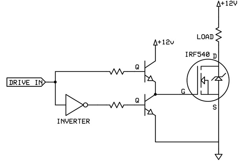
Power Mosfet Driver

N Channel Power Mosfet
- The power MOSFET can be directly controlled from micro-electronic circuits and is limited to much lower voltages than the thyristor, but is easily the fastest acting device.
- Above approximately 100V, conduction losses are high for the bipolar transistor and the thyristors.
- Switching losses in MOSFET are relatively much less.
- The MOSFET has a positive temperature co-efficient of resistance, hence paralleling of devices is relatively simple.
- In terms of current & voltage capability, the MOSFET is inferior to the current controlled devices of the bipolar transistor and thyristors family of devices.
